
Electrical conduit trenching for residential builds starts by setting the top-of-raceway burial depth and routing to match local code, often about 18 inches for PVC/nonmetallic and deeper in colder areas. They coordinate permits and file an 811 ticket to mark utilities before any excavation. Trenches are sized for both conduit and working room, with bedding and sand or fine-gravel haunching to prevent shifting. Backfill uses lifts and compaction, plus warning tape, and then inspection, as-builts, and cost estimates complete the job, so they can master the details next.

Many residential designs use 18 in. for PVC/nonmetallic conduit and about 24 in. for UF/USE cable, while colder climates may require extra depth.
Route selection also matters, since slab or driveway crossings can reduce cover with proper concrete protection.
When working in Los Angeles, confirm requirements for local construction codes so the final burial depth and routing meet the city’s prevailing standards.
Before any trenching begins, contractors and homeowners should coordinate the paperwork and the notification process so utilities are located and inspected in time.
Before trenching begins, coordinate permits and utility notifications early to ensure accurate locating and timely inspections.
In the U.S., each state uses a one-call center, accessed by dialing 811 or an online portal, and “dig laws” require advance notice 48–72 hours before excavation. Many local projects also need an electrical or building permit, so permit timelines should be aligned with ticket start dates.
After submitting a request, operators dispatch locators, and buried lines are marked with paint or flags, often by 7–8 utility operators. Our team should wait two to three business days, provide accurate project details, and plan excavation safety by respecting marks, using hand tools near the tolerance zone.
If markings fade, a re-mark request is required, and safety exclusion zones should be maintained around all marked utilities to reduce risk during conduit trenching.
Sizing trench width starts with planning for conduit working space, not just the conduit diameter, because installers need room for couplings, sweeps, and alignment during assembly.
Local utility standards often set a minimum trench bottom width—commonly 18 in. for primary or combined primary/secondary work, and sometimes 12 in. for residential service-only trenches—while NEC cover rules address depth rather than width.
Proper bedding placement and sidewall clearance are then used to prevent crowding, maintain support spacing, and allow safe pulling and marker placement above the conduit.
When planning conduit trenching, the trench width must serve two purposes at once: it must fit the conduit efficiently, and it must provide enough working space for placement, alignment, bedding, and safe installation.
In residential work, crews often plan trench widths 6–8 inches wider than the outside conduit diameter, keeping trench safety in mind while allowing compaction around the pipe. Many utility standards also set the conduit on the trench centerline to maintain equal side clearance, which helps operators tamp in 6-inch lifts to about 85% density.
For conduit maintenance later, the width must also support inspection of joints, slope, and drainage, plus room to grade smooth, undisturbed bedding materials.
For multiple conduits, horizontal separation is easier in wider trenches, with some standards requiring at least 18 inches at the bottom for grouped runs.
Minimum trench width rules determine how wide a conduit trench must be so the installer can place the raceway correctly and work safely around it. For primary or primary/secondary combined trenches, many standards require 18 inches minimum width at the bottom, with the conduit centered to suit the trench width. Residential service trenches are commonly allowed 12 inches minimum at the bottom, but local municipal codes can override general rules. For sole-use trenches with a single conduit, the width may be reduced to two times the conduit diameter, with a hard minimum of 6 inches. Because trench width scales with conduit diameter, installers should also expect wider excavations for pull and bending work.
| Application | Minimum trench width |
|---|---|
| Primary/secondary combined | 18 in bottom |
| Single primary | 18 in bottom |
| Residential service | 12 in bottom |
| Sole-use single conduit | max(2× conduit diameter, 6 in) |
Bedding and sidewall clearance are key details in trench design because they control both how easily the conduit can be placed and how well the backfill supports it over time.
Typical residential trenches run 6–8 in wider than the conduit outside diameter, balancing working room with sidewall stability. Some specifications demand far more, such as a minimum 24 in clearance, and geotechnical guidance may require at least 8 in clearance or a width equal to 12 in greater than 1.25× the pipe diameter, whichever is greater.
For bedding materials, crews often use about 4 in of sand or fine gravel under the conduit, then 4–6 in above.
In haunch zones, select sand is placed to 12 in over the top, compacted to about 92% in lifts no more than 6 in.
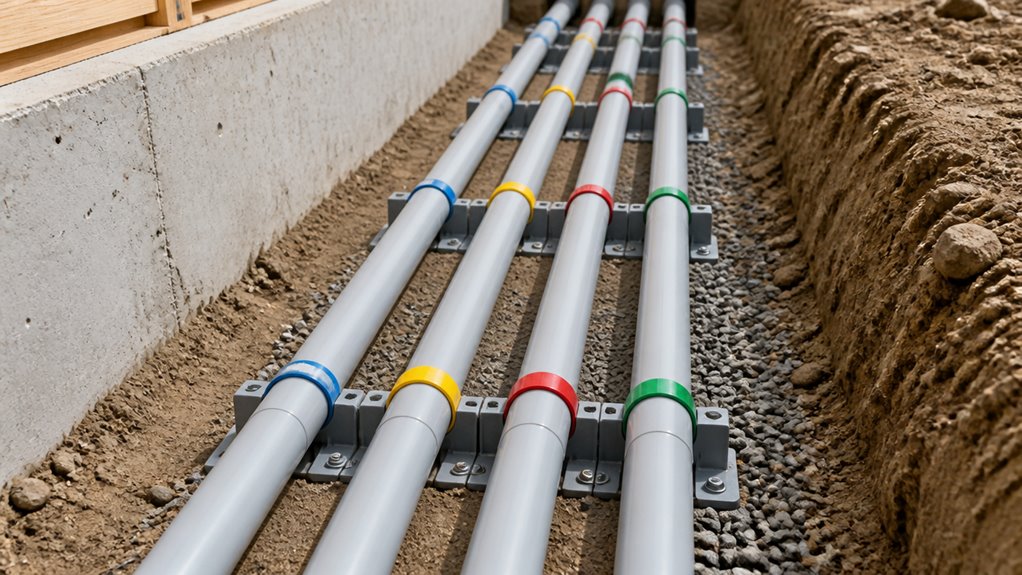
Proper conduit installation starts with correct bedding and support so the raceway will resist bending, crushing, and shifting over time.
After trench preparation and removal of rocks, roots, and debris, installers place bedding materials such as clean, compactable sand or fine gravel, about 3–4 in thick. The trench bottom is graded to a uniform profile, then the conduit is seated and gently compacted so PVC walls are not deformed.
For support, select backfill in sand or screened material, stone-free, and place it from the bottom up, compacting lightly around the conduit to avoid displacement.
Conduit type choices matter: use rigid nonmetallic PVC Schedule 40 for direct burial, and Schedule 80 where exposed or emerging from grade.
An excavating contractor’s focus on compacting helps maintain structural integrity during backfilling and leveling, which supports long-term conduit stability.
Designing conduit pull bends, expansion points, and the correct drain slope helps keep wiring from being damaged during installation and helps the raceway perform reliably after backfill.
Crews plan pull point placement by placing boxes or conduit bodies early along long runs, major direction changes, elevation shifts, and shifts to building entries.
Bend optimization focuses on limits: between pull points, total bends must not exceed 360°, and a run should contain no more than four 90° equivalents.
Layouts minimize total angle, avoid back‑to‑back 90° bends without an intervening pull point, and use long-radius bends to reduce sidewall pressure.
Where PVC faces thermal movement, expansion fittings are installed at underground-to-above shifts, anchored on one side, and set to a neutral position for the expected temperature range.
Expansion fittings should be kept away from tight bends.
When backfilling electrical conduits, the crew must place warning tape at the correct offset, commonly 12–18 in above the conduit or about 12 in above the top of the duct bank, so it gives an early visual alert before future digging.
The backfill should be installed in controlled lifts, often around 6 in near the conduit, with a protective bedding zone of sand or fine gravel and haunching that tightly supports the pipe before additional material is added.
Each lift must be compacted to reduce voids and settlement, using clean 4 in-minus (or finer) material where required near the conduit, then finishing the trench to grade and maintaining the prescribed tape location.
A dependable approach to warning tape placement keeps the tape at a consistent, measurable height above the conduit, so crews can locate and avoid damage without guessing.
Many North American specifications call for warning tape 12 in (300 mm) above buried electrical conduits, while utility standards may extend to 12–18 in, and European guidance places it about 200–400 mm above cables or protection pipe.
In residential work, tape materials and installation techniques usually target a location that also meets finished-grade depth rules, such as burying 12 in below grade or setting the tape 12 in above the marked utility, whichever controls.
When detectable tape is used, it must sit within equipment-rated detection depth, often 10–36 in below grade. Some cities specify about 8–12 in below final grade.
Crews should plan backfill lifts and compaction carefully because the way material is placed directly affects conduit support, long-term settlement, and the ability to locate utilities with warning tape.
Beneath conduit, they typically place a 4-inch bedding layer of sand or fine gravel, then keep the zone within 6 inches of the conduit free of sharp material.
Backfill material is often screened so rock stays about 3/4–1 inch, and municipal specs may require uniformly graded material passing a 1-1/8-inch screen.
For layering, many residential plans use 6-inch lifts, compacting each before adding the next, sometimes limiting loose lifts to 8 inches.
Compaction techniques commonly target 85% to 95% relative density, sometimes up to 96%, with tests verifying results.
Inspecting and documenting electrical conduit trench work typically begins with pre-inspection planning and a schedule that matches utility requirements. Existing underground facilities are located and field-marked within 10 feet before excavation. Then trenching waits until conduit or direct-buried cable is ready for installation.
Many utilities require formal inspection requests via standardized forms, with an inspector contact commonly within about three business days. With trench open and conduit visible, inspectors confirm burial depth, trench geometry, and bedding details using clear inspection techniques and documentation standards.
Yes—when utility regulations require deeper conduit depth than NEC, the utility rules control.
NEC cover values are minimums, but utilities may demand greater burial depth as a condition of service connection.
A designer should treat the most restrictive requirement among NEC, local code, and the utility standard as binding.
Before trenching, they should confirm the final depth with the AHJ and the utility provider, then schedule inspection accordingly to avoid failed approvals.
They confirm conduit routes by doing conduit mapping with records, as-built septic plans, and foundation drawings, then visiting the site for field verification.
First, they call for utility markings from 811 or local services, and they add private-locator checks for yard and detached lines.
Next, they probe suspected sewer and laterals, and they verify tank and drainfield locations with equipment or targeted test holes.
Finally, they keep trenches outside septic and footing zones, marking a safe corridor on the plan.
For multiple conduits, trench width is typically set so there is working room beyond the total conduit footprint. A common rule is trench width at least equal to the total horizontal spread of all conduit outside diameters plus about 2 inches overall, meaning roughly 1 inch clearance each side.
Many utilities also impose minimum trench depth and require clear conduit spacing, often leading to 6–12 inches at the bottom, sometimes more for groups.
Inspectors typically require detectable, bright red warning tape over buried PVC conduit, placed about 12 in (300 mm) above the conduit.
Coincidentally, this depth matches common utility and installation practices, so inspections go smoother. The tape is usually labeled with legends like “Caution Buried Electrical Line Below,” and it must be detectable for locating equipment.
Exact placement, width, and wording still follow the local AHJ or utility standards.
Expansion joint spacing should be set by NEC 352.44 trigger travel: where a PVC run between securely mounted items can move 0.25 in or more, expansion fitting placement is required.
For typical PVC assumptions, that happens when straight runs are about 25 ft+ with ~60°F+ temperature change, or roughly ≥6.25 ft for a 100°F swing.
On long runs, manufacturers divide total expansion by common fitting travel (~4 in) and space evenly.
Near building entries and risers, add a fitting just below the first rigid enclosure, like the meter or panel.
Electrical conduit trenching succeeds when depth, routing, and installation practices align with code and local utility rules. For example, many jurisdictions require the top of the raceway to be buried at least 18 inches, helping protect cables from normal digging and weather impacts. After excavation, careful bedding, properly sized trenches, and correctly planned pull bends reduce future failures. Finally, professional inspections, as-built records, and accurate cost estimates confirm the work was built to last, with confidence.
Skip to content